


aussieslotter
-
Posts
2,523 -
Joined
-
Last visited
-
Days Won
64


aussieslotter's Achievements
")


-

Scorpius MPD multi purpose multi protocol decoder.
aussieslotter replied to aussieslotter's topic in Scorpius
So MPD V3.0 is complete. That was simply a redesign of the super capacitor circuit. John came up with a great idea of a multi purpose 4 pin port that can handle UART Comms, or a hall sensor, or an OLED driver or a BLDC driver (brushless motors), very flexible and very multi purpose. We also added a snap off BEMF mini pcb that solders to any motor can to keep power clean on the decoder. This was a Carrera idea I’ve copied. Around 10 changes all up on V2.0 and V3.0. A 7 week wait now for new boards. Pic 1: The new multi Comms port. Pic 2: Wiring diagram. Pic 3: Snap off BEMF protection PCB 13.3x8mm.


-
Scorpius MPD multi purpose multi protocol decoder.
aussieslotter replied to aussieslotter's topic in Scorpius
Hi Guys, We have made 7 lots of hardware changes to the MPD design. Here’s a progress pic. Still 22.3x13.3x2.0mm. Sadly we didn’t get to include the second radio chip as mentioned previously due to cost, complexity and increase in board size. However we did add or modify some things. Improvements include: 1.Main onboard SMD capacitor upped to 141uF 2.Pin connections for lighting super capacitor which will connect on a fly lead. 3.Creating a new multi purpose 4 pin port that can port the following: a. Comms (wired) b. OLED screen c. Hall sensor d. Brushless motor driver connection. You can choose any of these but you can only choose one. 4. Addition of a snap off board that solders to your motor can for better back EMF protection. Yet to be added. 5. Reconfiguring existing LED circuitry and drivers. 6. Reconfiguring diodes to better suit Carrera compatibility. 7. Reconfiguring power in and motor drive out pin positions to better suit Scorpius and Carrera.


-
Scorpius MPD multi purpose multi protocol decoder.
aussieslotter replied to aussieslotter's topic in Scorpius
Hi Guys, V2.0 schematic designed today. We upgraded the 3 pin hall connection to 4 pin so we can now accomodate BLDC (Brushless LC injection), OLED, Hall sensor, and COMMs (UART connection), this allows hardwired connections to piggy back to various hardware for future projects. We also added 3x 47uF caps in place of the 10uF (so 14 times more capacity) and added 2 pins for a super cap for lights to stay on long time whilst crossing dead spots. We also reconfigured the power in/out to suit Carrera. It will still be DPR (Scalextric) compatible. LED drivers are upgraded to mosfet type rather than transistors. John was able to do all this and yet still maintain the same size of just 22.3x13.3mm! Unbelievable. Next stage is to re-design the actual board. Stay tuned.
-
How’s your firmware stack up? Bootloader Blues? DFU disasters… the list is endless. .
-
The only 2.4GHz digital system with real time lapcounting and 1/1000th of a second accuracy, glitch free with minimum car hardware with just one 3mm LED. The unique test loop developed by Scorpius can test 5 brands of digital systems with ease. The loop allows me to test 10,000 laps in under 90 minutes. On a normal track this would take 2 eight hour days with a human driving it. And yes it wasn’t a straight forward exercise. We had to play with sensitivity levels and algorithms for weeks to perfect it. The test gear: Test car: NSR Lola 21k motor Track voltage: 22.0V The diameter is precisely 1.820m. Lap times 0.53 seconds. Circumference is 5.715m precisely. 1/0.53x5.715m = 10.78m/s or 38.8kmh Destruction limit testing is the next phase. Rick
-
Nitrous for Carrera Digital Here’s how it will work. *Scorpius controller sends global wireless commands. *Scorpius MPD chipped car and Scorpius to Carrera wireless relay both receive command. *Relay sends to Carrera receiver. *User has full benefits of Carrera 100% native and Scorpius protocols. *All existing race software and apps completely compatible. Primary benefits throttle: 1. 256 step throttle resolution for superior control and reduced lap times. 2. 256 brake resolution for superior control and reduced lap times. 3. Throttle mapping 4. Throttle Minimum speed. 5. Throttle choke 6. Throttle choke bypass 7. Throttle traction control 8. Throttle adjustable brakes on the fly 9. Throttle map selection on the fly. 10.Throttle speed limiter (pits or learner mode) 11. Can be reconfigured with Carrera Wireless throttle protocols. 12. Can be used in conjunction with Scorpius Wireless Analogue module to run analogue cars in traditional analogue track. Primary benefits Scorpius MPD car decoder: * Can be operated by Scorpius controller for Nitrous mode or in Native mode using any Carrera controller set up. * Telemetry as follows: 1. Car ID 2. Car PIN 3. Motor drive PWM 4. Brake drive PWM 5. Sector incl lap count request 6. Lane 7. Lane change request status. 8. Version Number 9. Tacho RPM 10.Back EMF in Volts 11.Current draw in amps 12.Torque in N-m 13.Power in watts 14.Fuel level in litres 15.Tyre level % 16.Brake pad level % 17.Damage level % 18.G force X axis 19.G force Y axis 20.G force Z axis 21.Sound preferences 1-8 22.Lighting preferences 1-8 23.Driver Name 24.Lap time 25.Best lap time 26.Laps *Free wireless updates using phone. *Configure brakes and throttle mapping when used natively. *Full functioning lights. *Scorpius, Scalextric full compatibility. *Powerful 10A motor drive *In car simulations as follows: 1. Tyres 2. Brake pad wear 3. Simulated tank weight. 4. Simulated fuel usage based on electricity usage not throttle position. 5. Simulated damage using G-force detection.

-
Hi Gentlemen, This is for any motor and has nothing to do with it being digital or analogue. Back EMF detection (it’s just the leftover voltage retuning to the source) along with some calculations can give us a tool that can show us: RPM Torque Power Just like a 1:1 dyno test As Back EMF is now included in telemetry you can work out the torque if you know the armature resistance. This video explains it very clearly. Now we have not just a real time wireless tacho we also have the same for torque. Power. Once you know the RPM and torque etc you can work out the power. And like all telemetry this can be shown on the OLED screen.
-
Fuel burn based on actual usage of electricity. The most realistic you can get. Up until now there’s been 3 ways slot car systems work out fuel consumption. 1. Time or laps. Very primitive and not very realistic. 2. Throttle position. Does not take into account sensitivity knobs on the controller. Trigger lag, sometimes you move 5mm or more before the car even starts to move. Doesn’t take into account the motors natural throttle map ie the motors power map is probably not linear. 3. PWM. (Scorpius) This is the pulse wave modulation signal (0-255) given to the car decoder to execute after all previous manipulations have taken place. ie sims, throttle limiting and throttle mapping. However you could run any motor and the system wouldn’t know the difference. So the PWM method is the best we have but can we do better? 4. Current detection. At the end of the day the car uses real energy, in this case electricity. Why not use this data to calculate fuel usage? But how to calculate it and how to gather the information required to process the algorithm? Because we have a purpose made current sensing resistor in the circuit of the new MPD, we can calculate fuel 100 times a second based on how much energy the motor actually uses, nothing else matters. So if you’re using big motors or are heavy handed you will use more fuel and therefore will have to pit and have a longer refuel time. So there you have it. Virtual fuel based on real energy consumption . Another world first by Team Scorpius.

-
Hi Guys, Ever head an event where you need to equalise cars? I’ve held a couple of events with handout cars. NSR cars in one event and SCX Nascars in another event. Motors vary in tolerances and therefore speed. This makes for an unequal event. So fast forward to 2023. We currently have a design layout which includes Back EMF detection. This circuit detects a pulse in back the back EMF that feeds back from the motor to the decoder where the magic happens. The MPD is not just a car decoder. It’s an advanced micro computer for slot cars if you like with its own proprietary real time operating system. Information is analysed. RPM is shown on the plug in plug out OLED. screen or you can use your PC (and later app) to see RPM. Now use the configuration program on your controller or PC to limit tech, ie 21,000RPM. Upload to car and now you have all cars equal RPM. If that isn’t enough you can handicap any car using speed limiting now settable in car not just on controller. The great thing is all these functions are purely firmware. All with one piece of hardware, the MPD.

-
Hi Guys, Sound for slot cars is nothing new. These days it’s generally driven by a Race management system on your PC generally connected to a single external speaker. Problem 1: Car location and sound are generally in different locations making it unrealistic and maybe even confusing. Problem 2: Sound is generally when a car crosses the finish line only. Problem 3: Sound is generally mono generally from one speaker or small pair of speakers close together. What if we could have location specific sound as the car(s) move around the track? ie a sound source physically located adjacent the sector each car is in? What if the car could talk directly to speakers without wires or software programs? This would involve breaking the track into sectors. Scorpius already has this. We also need a way of identifying these sectors and making this data available wirelessly. We can do that too. Next we need a way of capturing the information (RF) and then using this data to trigger a number of sound channels using a number of 5V trigger wires. Scorpius also has this. So we have all the hardware except for: 1. An MP3 sound module/card. 2. A speaker. I found a good quality speaker for $$25 and a quality 8 channel MP3 player with amplifier for $25 also. Add in the cost of the MPD receiver at $69AUD plus tax/customs/delivery and you have each unit coming in at $130AUD or 65GBP, or $85USD in a DIY kit. Let’s mount both the MPD receiver and the MP3 audio module within the speaker. Done. Now let’s add a 12V power supply. Ok here we need wires. Oh well it happens. Wireless electricity is still a way off. Next we need to build a surround sound network without burdening the existing wireless comms in any way. And without burdening the RMS in any way. ie no additional dongles or processing. We have a choice to use channel 25 (RF) or Bluetooth to transmit from car direct to speaker. Yet to be determined. Ok let’s use the cars existing telemetry which can be accessed by any device. Within the telemetry we can include the trigger for sound by each car as it enters each sector. Done. The car decoder has a preferred lane change registry already for each Lane Brain (every lane changer). We can add sound preferences also. Up to ten sound choices are possible. The choice is included in telemetry from 0-8 as it’s an 8 channel sound system. The receiver, surprise surprise, another MPD captures and decodes this and sends triggers to the required channel on the MP3 audio module (with its own sound card) to access the required sound. Each driver can have their own unique selection of sounds for each sector. Sound could be switched on/off and volumes for each station adjustable on the speaker itself. You could just use certain sectors and ignore others so it doesn’t get too noisy. So there you have it. The worlds first real time 8 channel true surround sound for slot cars.


-
This is for any motor and has nothing to do with it being digital or analogue. Back EMF detection (it’s just the leftover voltage retuning to the source) along with some calculations can give us a tool that can show us: RPM Torque Power Just like a 1:1 dyno test As Back EMF is now included in telemetry you can work out the torque if you know the armature resistance. This video explains it very clearly. Now we have not just a real time wireless tacho we also have the same for torque. Power. Once you know the RPM and torque etc you can work out the power. And like all telemetry this can be shown on the OLED screen. The video explains it much better. https://youtu.be/ndseqKIlR9c?si=Z1yoyoUPoH0lvK_G
-
Wireless slot car network. Here’s how each Scorpius unit talks to each other. https://drive.google.com/file/d/1Lo-AeXAz96aRxlJCSbFCOJDUGtkrrznw/view?usp=drivesdk

-
To put car into different modes simply tap the car shell on any part of the body and let the accelerometer do the work. Amount of taps for various modes: DFU: 3 RF and RF: 4 Configure car decoder settings : 5 RF and BT: 6 Bootloader: 7 Filters have been arranged to prevent any track activity being interpreted as a tap command. RF = Scorpius 2.4Ghz proprietary BT= Bluetooth (5.3) Choice 1: Use the 832 chip for RF throttle to car comms. Use the 805 chip to send telemetry to phone app. Choice 2: Use the 832 chip for RF throttle to car comms. Use the 805 chip to send telemetry to dongle then onto the RMS of being used. This frees up the 832 for ultimate use of speed. We can also now get 10 times more telemetry back to the PC enabling accelerometer readings, current detection amongst others to be added without burdening the system using the 805. What can be achieved with this is true real time sims for fuel and tyres etc, at PWM level not laggy throttle position readings. This can be done in the RMS or even on the car chip itself. Rick For PC connection For phone connection


-
Hi Charlie, Basically any function of the race software can be utilised. It is however tied into Race Coordinator software only. Rick
-
Scorpius MPD multi purpose multi protocol decoder.
aussieslotter replied to aussieslotter's topic in Scorpius
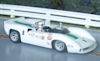
MPD Specification/Functionality V2.0 Hi Lads, In the last few weeks around 10 hardware changes have decided on. This is because we doubled up in radio chips, deleted the hall sensor, added an OLED display driver just to name a few. The OLED could be used to input or read data on the MPD. The OLED is 0.5x0.5” and is placed in the top of windscreen on side opposite to driver. Now use the Scorpius controller knob to quickly scroll through the following: Car number # or ID, fuel, brake pad and tyre levels, fuel burn rate, damage level, tyre type, max CG force, engine tacho, brake setting, throttle map. Fair Dinkum can you imagine scrolling to tacho, lifting the rear wheels off the track and revving it to see your real time engine speed in the windscreen of your favourite car. We also upped the 10uF SMD capacitor to 100, separated data outputs in each of the SSD drivers, also Carrera drivers. This creates another 2 light 5V channels. And the ability to be a 2 lane analogue lap counter as it was one data circuit previously. Length will still be under the original target of 26mm at just 25 currently 22.0mm Size: 25.0x13.3x3.0 Layers:2 Sides used: 2 Radio/Microprocessor 1: Nordic nRF 52832 6x6mm. Radio/Microprocessor 2: Nordic nRF 52805 WLCSP 2.48x2.46mm. Data rates for both: 1MB/sec Range: 50m Motor Drive 1: 10A Motor Drive 2: 10A Brake Drive: 8.8A Power in:8.5-18V AC/D Scorpius photo sensor inputs: 2 (1 mounted on board, 1 on lead). Carrera IR LED outputs: 2 (1 mounted on board, 1 on lead) * Scalextric Sport Digital LED outputs: 2 (1 mounted on board, 1 on lead) * *Can be configured as lights. Light outputs**: Headlights and tail/brake lights. **All lights and IR LED outputs can be configured as: Tail/brake, headlight, flashing light, exhaust flame simulator. Accelerometer: 3 axis OLED display driver: Yes Tacho: Via Back EMF detection Main capacitor:100uF, surface mounted. Motor PWM steps: 256 Brake PWM steps: 256 Compatibility: Scorpius, Carre/.kra, Scalextric Sport digital, Ninco*, SCX* *Scorpius controller required. Pic of some of our MPD loaded ThunderSlot Lola chassis test cars with 21.5k motor.


